In order to achieved a desired optical functionality in an application, it is critical that key use parameters are communicated. Understanding the filter function and use conditions allows the filter design team to create a filter specification that will ensure the functional requirements are met by a filter that is manufacturable under the commercial constraints (cost, lead-time, volume) of the customer (see our technical note “Filter vs Functional Specs”).
Spectral Bandshape:
In general, the desired functional spectral performance over the full operational wavelength range must be defined for an optical filter. The spectral information required varies for different types of filters including band pass filters (BPF), edge pass filters (long pass and short pass, LPF and SPF), notch filters, dichroic filters (long pass dichroic and short pass dichroic, DLP and DSP) and telecom filters including BPF, LPF, gain flattening filters (GFF), and solid or single cavity etalons (SEF or SCF).
The following spectral parameters must be specified in addition to the other parameters discussed in detail below such as AOI, CHA, substrate type, substrate thickness and tolerance, filter dimensions (un-mounted or mounted and mount size) and tolerance, polarization requirement, filter clear aperture, surface quality, surface figure, as well as the environmental operating conditions.
(1) Band pass filter
- passband transmittance wavelength range(s) and level(s)
- ripple spec (allowed transmittance variation) for the pass band range(s) if applicable
- reflection or blocking band range(s) and level(s)
(2) Edge pass filter (long pass and short pass)
- passband transmittance wavelength range(s) and level(s)
- ripple spec (allowed transmittance variation) for the pass band range(s) if applicable
- reflection or blocking band range(s) and level(s)
- cut-off value and/or edge steepness.
- for the definitions of cut-off and edge steepness, please refer to Iridian’s “Edge Filters for Raman Spectroscopy” application note.
(3) Notch filter
- reflection or blocking band range(s) and level(s)
- passband transmittance wavelength range(s) and level(s)
- ripple spec (allowed transmittance variation) for the pass band range(s) if applicable
(4) Dichroic filter (long pass dichroic and short pass dichroic)
- passband transmittance wavelength range(s) and level(s)
- ripple spec (allowed transmittance variation) for the pass band range(s) if applicable
- reflection or blocking band range(s) and level(s)
(5) Gain Flattening Filters (GFF)
- target transmittance curve data along with desired Peak-to-Peak Error Function (PPEF)
(6) Solid Etalons and Single Cavity Etalons
- the free spectral range (FSR), Finesse, and FSR temperature variation
- for Single Cavity etalons the -3dB bandwidth (FWHM) needs to be specified.
Angle of incidence:
Angle of Incidence, or AOI, is the angle subtended by the nominal beam and the normal to the surface which it is incident upon.
Cone half-angle, or CHA, is the angle subtended by the nominal beam and the maximum (or minimum; the beam should be nominally symmetric) angle from that beam.
Cone full-angle or cone angle, is the angle subtended by the maximum angle in the beam and the minimum angle in the beam.
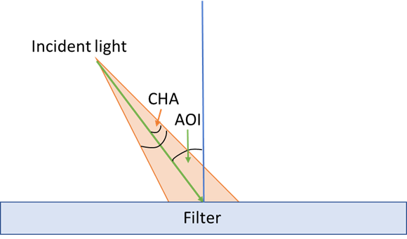
Field of view, or FOV, is the angular range over which a collimated or uncollimated beam is incident on the filter’s first surface, measured relative to the surface normal at the surface that the beam is incident upon. While similar to CHA, a non-zero FOV may result from a convergent or divergent beam or a use condition in which collimated light may vary in its angle of incident over time.
Changing the AOI, CHA, or FOV of your incident light will change the spectral response of the filter. For more information on how the edge pass filters respond to changes in AOI, please review our technical note Edge Filters for Raman Spectroscopy. For a custom filter, it is important to provide the AOI and CHA/FOV ranges in order for the filter design engineer to optimize the filter to work over these ranges.
Beam size information, and in the case of a filter with a CHA, the distribution of light over the angle range (e.g. Gaussian versus flat-top) is useful when providing the functional use specifications.
Polarization:
When light is incident on an optical filter at a non-normal angle of incidence, the polarization of the light can be described by two orthogonal vector components associated with the orientation of the electric field of the light wave. The polarization is referenced to the plane of incidence (the plane defined by a vector in the direction of the beam and the normal to the surface) and contains both the incident and the reflected light rays. The polarization component that is perpendicular to the plane of incidence is called the “s” component, and the component that is parallel to the plane of incidence is called the “p” component.
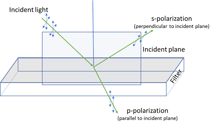
In many instances the incident light is unpolarized so the filter must be designed for use in random polarization (that is, all specifications need to be met for either s or p polarization state) but in cases where the incident light is polarized or where the filter functions as a polarizing beam splitter it is important to specify which polarization is relevant.
Surface Finish/Quality
The finished surface quality requirement needs to be defined as part of the non-optical quality specifications. Iridian’s works to scratch-dig standards based on the US Military Standard MIL-PRF-13830 and/or the ISO10110-7 standard.
It is important to define surface quality to meet a specific functional need rather than just as a cosmetic requirement as this specification can strongly influence yields and costs. Do not just use a “typical” standard from an optics catalogue as this will likely be overly stringent and perhaps render the filter not feasible. If in doubt please discuss functional use with the filter design team so a specification can be agreed upon that will provide functional success at an achievable and reasonable technical and commercial cost.
Surface Figure/Wavefront Error
In many applications (for example imaging) it is important to preserve the wavefront of the light as it is transmitted and/or reflected by a filter. It important to not simply rely on specifying flatness of the filter surfaces in hopes of achieving desired transmitted or reflected wavefront error/distortion (TWE/RWE) performance. – this can be insufficient or in many cases unnecessarily constraining to the filter design and manufacture. For a detailed overview on specifying these parameters please see our “How to Specify Surface Figure” guide.
Substrate and filter dimensions:
Iridian can provide filters on substrates such as Borofloat, Schott BK7, Fused Silica, WMS-15 glass ceramic, silicon, germanium, sapphire among other glass or glass-like substrates. The choice of substrate is best left to the filter designer as this can influence functional performance due to differences in thermal drift, stiffness, etc. along with influencing cost and availability. If a specific substrate is required it is important to indicate what functional need is driving the need to specify a particular substrate (such as the need to match CTE to the surface on which a filter is matched, for example).
Substrate thickness can be specified and requested. Some standard thicknesses are available depending on the substrate type. Please check with our sales team for the available thickness.
Iridian can process custom filter sizes in round shapes, rectangular or square dimensions to your required size. The dimension tolerance should be provided.
Filter mounts with standard diameter 12.5mm and 25 mm are typical and custom diameter can also be requested as well.
Clear Aperture:
While the optical coating often extends to the edge of every filter, the clear aperture (aka functional or effective aperture), the aperture over which all spectral specifications are met, will be less than the physical dimensions for each filter – there will be edge effects even on filters that have been coated on a larger substrate and cut to final size.
For unhoused, round filters, the clear aperture is typically guaranteed to be greater than 90% of the outer diameter. For square and rectangular parts, the guaranteed clear aperture will typically be greater than 80% of the filter’s transverse dimensions and is elliptically shaped. The clear aperture of a housed filter is dependent on the size and thickness of the housing ring. All filter specifications are guaranteed only within the clear aperture region.
Orientation of the filters:
To maximize intended transmission and blocking and to minimize auto fluorescence in bio-analytical applications, filters are recommended to be oriented in such a way that the light is incident on a specific surface of the filter. Usually, the optimal orientation is such that first surface that the light is incident upon is the primary coating – that is, the coating that provides the primary bandpass, edge-pass, notch, or dichroic reflector function – rather than the backside coating (typically and anti-reflection coating (AR) or extended blocking coating).
When required, ring mounted filters can have an arrow on the mounting ring, whereas the un-mounted filters are indicated with either scribed or diced mark on one surface or edge of the filters. Typically, the filter arrow points to the first surface upon which the light should be incident but this can be customized upon request for non-standard filter builds.
Specification template (example):
Use conditions
| Angle of Incidence | deg | tolerance (+/- deg) |
| Cone half angle | +/- deg | |
| Operating Temperature range | Min (C); Max (C) |
Spectral requirements
| Transmission range | Min (nm); Max (nm) | may be multiple ranges for a multiband filter |
| Transmission level | dB; % | specify average or absolute |
| Reflection (or blocking) range | Min (nm); Max (nm) | may be two ranges - one on each side of a bandpass filter |
| Reflection (or blocking) level | dB; %; Optical Density (OD) | specify average or absolute |
| Transmitted and/or reflected wavefront error (T/RWE) | nm | specify RMS or P-V; can power/tilt/piston be removed from calculation? |
| Polarization | random; or s or p | |
| Polarization dependent loss (PDL) | dB |
Physical requirements
| Lateral dimension | diameter or length and width (mm) | tolerance (+/- mm) |
| Thickness | mm | tolerance (+/- mm) |
| Clear aperture | Min (mm) | |
| Surface quality | defect or scratch dig allowance | ISO10110-7 format or S/D |
| Substrate type | Fused Silica, BK7, etc. | only specify if there is a specific need and explain reason for specifying |