LiDAR and Optical Filters – Helping Autonomous Vehicles See More Clearly
“What’s a ‘steering wheel’?” At the present time this would be a very strange question to hear asked from anyone who has driven, ridden in, or even seen a car but in a couple of decades this may not seem so unusual. The evolution of increasingly affordable and capable sensing and imaging systems combined with the desire to create safer, more efficient transportation systems is driving the development of autonomous vehicles (pun intended). LiDAR is a key technology that will eventually help carry this growth through to “Level 5” autonomy : no steering wheels, no brake pedals, no human intervention in driving.
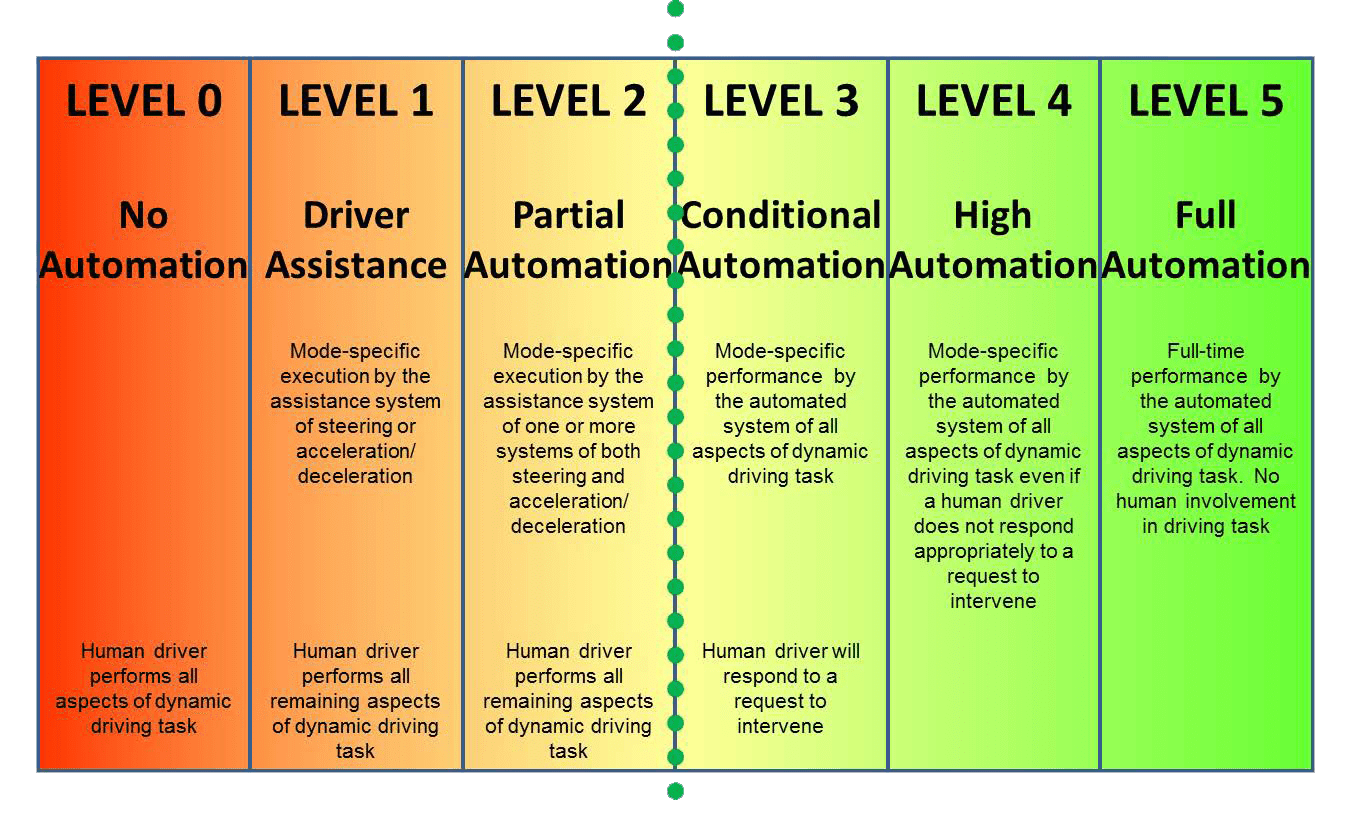
Fig.1 Levels of Automotive Automation – SAE International J3016 Jan 2014; dotted green line denotes current state-of-the art
Many high-end (and increasingly middle and lower end) cars already have some advanced driver-assistance systems (ADAS) to aid with collision detection/avoidance and lane departure warnings, providing “Level 1 to Level 2” autonomy, with some proto-type/pre-production vehicles, such as the Audi 8, capable of fully hands-free operation (“Level 3”). Some companies like Google/Waymo and Volvo are skipping the interim steps and working on development of fully autonomous “Level 5” vehicles in the belief that consumer traction will only be gained with fully automated vehicles, not a hybrid approach. It is too late to close the door as the “autonomous horse” is already out of the barn.
Enabling autonomy
Automotive autonomy is fundamentally about vehicles responding automatically – navigating, braking, accelerating, steering – to cues from their environment; whether other vehicles, road conditions, pedestrians or other potential, and unpredictable obstacles or hazards. The old adage “you can’t manage what you don’t measure” applies to automotive autonomy; vehicles need to measure their environments and their place with in these dynamically changing scenes by accurately sensing, imaging, and detecting their conditions and surroundings in order to manage their way safely through the entire road infrastructure and surrounding environs.
There are many sensor technologies that can contribute to creating a dynamic 3D map of a vehicle and its surroundings but the three key technologies that provide guidance for automation of steering, accelerating and braking (that is, on-road driving) are RADAR, cameras, and, more recently LiDAR. There are pros and cons to each of these technologies (see Figure 2).
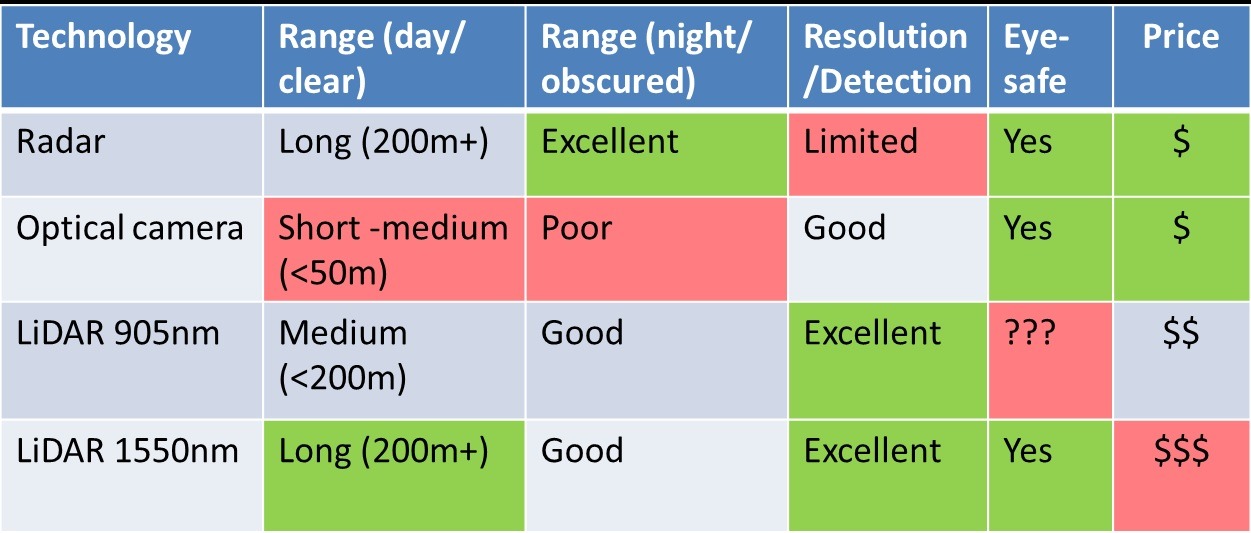
Fig.2 Imaging sensor technologies for autonomous vehicles
RADAR (both mid and long range) can measure distance and relative velocity of objects at distances of up to 200m in all lighting and environmental conditions but, due to the long wavelengths of radio waves and the broad beams used, is incapable of differentiating and resolving the details of the objects that are detected (such as the direction a motorcycle is facing or whether a person is walking toward or away from the path of a vehicle).
Optical cameras can provide accurate images of a scene but have limited range, do not provide distance and relative velocity information, and are limited to functioning in well-lit conditions with good visibility. The vision provided by cameras most closely replicates that of human drivers but we want and need autonomous solutions to be better than we are at seeing the driving environment.
LiDAR is the newest kid on the block when it comes to automotive sensing but is far from a new technology. LiDAR is an acronym for Light Detection and Ranging and was established as a defense technology 50 years ago (for secure distance measurement and targeting applications).
Fundamentally, LiDAR involves sending light (as opposed to radio waves used in RADAR) out from a source and measuring the returned beam. Because the wavelengths used (typically 905nm or 1550nm) are many orders of magnitude shorter than radio waves, a much finer resolution image can be formed of the objects intersected by the incident light. Additionally, unlike cameras, LiDAR systems illuminate the surroundings and so are not reliant on ambient lighting working equally well day or night. Working at wavelengths longer than the visible also provides an advantage in reduced visibility conditions (such as fog or rain) although the very long radio waves of RADAR have a significant advantage in these conditions. Eye-safety is another key factor when using laser illumination. The lower power of the 1550nm sources addresses this concern. Last but not least comes price; while prices are dropping LiDAR systems are still more expensive than either RADAR or camera options. While 905nm LiDAR systems can use standard CMOS or CCD Si detectors common in camera technologies, 1550nm systems employ InGaAs detectors which are still much more expensive. It is expected that as the demand for these longer wavelength detectors increases prices will come down making this option commercially viable.
There are several different architectures and methodologies employed in LiDAR systems; from micro-mechanical mirrors (MEMs) to solid state “flash” LiDAR. However in most configurations the LiDAR system uses time-of-flight to sense distances to objections intersecting the illuminating beam. Time-of-flight systems measure, through one of several different methodologies, the elapsed time from launch of a pulsed beam of light to detection of the reflected returned beam and uses this time to calculate the distance traveled.
Distance = Velocity [c/na] x Time of flight [(tr-tl)/2]
c – speed of light; na – refractive index of air; tr – time when pulse returns; tl – time when pulsed was launched
By continuously scanning the surrounding environment and using this time-of-flight distance information a real-time 3D point map can be generated. The resolution achievable with LiDAR mapping means that this map can not only show the presence of an obstacle but also allows for image recognition to determine what the object and how it is moving within the environment. For example, if the object is another car, is it parked or moving and what direction is it facing (is it going to enter the driver’s path or is it driving away).
For these systems to operate properly and generate accurate images, it is critical that the detector is able to distinguish and discriminate the returning beam from other light sources such as ambient daylight, street lighting, head-lights, and even other LiDAR systems. This is where optical filters play a role.
Don’t forget your sunglasses
If detectors are the “eyes” of a LiDAR system then optical filters are the “sunglasses” – reducing glare to allow the eyes to see what they are looking for without the background noise. In practice, this means two of the primary functions of optical filters in these systems are a) to reduce scattered light, ghosting and back reflections, and b) to provide wavelength selectivity to block all light from reaching the detector with the exception of the launched LiDAR beam, providing “more signal, with less background” to the detector.
Reduction of reflected/scattered images can be achieved by effective low loss anti-refection (AR) coatings. These coatings are designed to provide low reflectivity (<0.5%) over the wavelength and angular range that the optics to be coated (lenses, windows, filters) need to operate.
Wavelength selectivity requires a more complex optical filter with as narrow a high transmission band (the signal) as possible with broad and deep blocking of all other extraneous light (the noise). This band-pass filter functionality is very common in many optical applications. As mentioned above, automotive LiDAR systems typically operate at either 905nm or 1550nm; in either case the desired band-pass filter will have high (>90%) transmittance at the “launch” laser wavelength. The difference lies in the range over which Si or InGaAs detectors operate (~300-1100nm and ~900-1700nm respectively) as this defines the region over which deep (preferably <0.01% average (OD4)) blocking of the background “noise” is required.
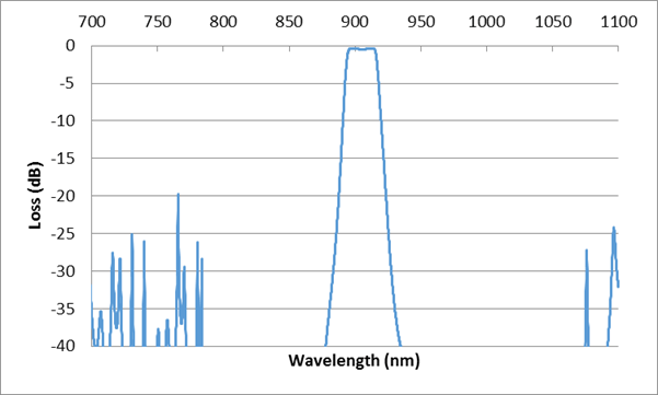
Fig.3 905nm band-pass filter spectral performance curve
There are several aspects of LiDAR systems intended for automotive use that present special challenges to optical filter and coating designers and manufacturers. First among these is the operating environment; these filters may see a broad temperature range (-40C to +80C) and, particularly in the case of windows, may be exposed to rain, ice, road salt, and all of the other elements encountered as a car drives down the road. This uncontrolled environment drives the need for thermally stable filters as well as filters composed of very robust and reliable coatings. Additionally, these filters need to be able to operate under these conditions without maintenance or calibration for the life of the vehicle. Fortunately, similar concerns existed for optical communications filters (captured in Telcordia reliability standards) so these problems are well understood and largely solved by filter manufacturers; especially those coating thin film filters with energetic sputtering deposition techniques.
Optical cameras can provide accurate images of a scene but have limited range, do not provide distance and relative velocity information, and are limited to functioning in well-lit conditions with good visibility. The vision provided by cameras most closely replicates that of human drivers but we want and need autonomous solutions to be better than we are at seeing the driving environment.
Secondly, many LiDAR systems employ a wide field-of-view (FOV) at the detector enabling scanning over a broad scene but creating a requirement for optical filters to function over a wide angular range without loss of performance. Multi-layer interference films inherently experience a “blue-shift” to shorter wavelengths with increasing angles of incident light and, to quote Star Trek’s Scotty, “ye cannae change the laws of physics”. To address this wavelength shift, the filter can be “over-designed” to have a pass-band that is extended to the red side of the laser wavelength to maintain transmission of the laser over a broad angle range. Unfortunately, this compromises the blocking as it results in a broadened pass-band at any one angle of incidence. However, new material sets have been developed with improved angular insensitivity, enabling the design of narrower filter solutions than were previously available.
The Road to the Future
In addition to the technical challenges mentioned above, when automotive LiDAR systems become ubiquitous, huge commercial pressure will arise for both a low-cost and high production capacity filter supply chain. Finding a technical solution is not enough; it is necessary to develop a solution that is scalable to support what are sure to be rapidly growing needs for “cheap sunglasses” for all of the autonomous “drivers” soon to hit the roads.
There is still a long road ahead of us before the streets are filled with “Level 5” autonomous vehicles but we have begun down the path and are already reaping the benefits of automotive photonics sensor technologies and the optical filters that enable them to see clearly.