Raman Spectroscopy
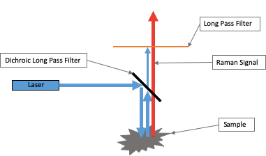
Raman spectroscopy probes the molecular vibrational and rotational modes of a material in order to detect and identify the material. Typically, laser light is incident upon the material and the scattered light is measured.
The excitation source (laser line) intensity is often to orders of magnitude greater than the Raman scattered signal. Therefore, edge pass (or notch) filters are required to block the Rayleigh scattered laser light while transmitting the red-wavelength shifted (Stokes) and/or the blue-wavelength shifted (Anti-Stokes) Raman scattered signal.
This technical note first defines various terms useful in describing Raman edge (or notch) filters. After this, there is a discussion on how to best use the edge pass filter to ensure that the desired optical performance is obtained for the intended application. Different parameters that affect the measured edge pass filter transmittance are described including angle of incidence, light cone incident upon the filter, polarization of light and laser line wavelength variation
Optical Density
Optical Density (OD) is a measure of the blocking ability of an optical filter. As light passes through the filter, some of the light is transmitted while the rest is either reflected, scattered or absorbed. Optical density takes into account all forms of light attenuation and is defined as:
OD = -log10T
where ‘T’ is the transmittance of a filter. The OD value of a filter is numerically equivalent to of the filter’s transmittance when specified in dB.
Examples of different OD levels versus T[dB] for a Long-Pass Filter (LPF) are shown in the figure below. Unless otherwise stated, this and the following figures assume collimated, monochromatic light incident upon the filter with a negligible instrument (detector) resolution.
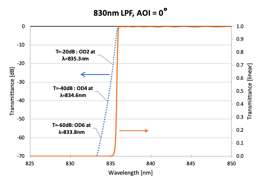
Example of a typical Long Pass Filter (LPF) shown with the filter transmittance in dB and linear scales. Different OD levels corresponding to T[dB] are also shown.
Edge Steepness
The edge steepness of an edge pass filter is defined as the spectral width (specified in units of ‘%’, ‘nm’ or ‘cm‑1’) between two points on the slope of the edge pass filter. Hence, the smaller the edge steepness of a filter, the sharper the transition from passing light to blocking light (and the more challenging it is to fabricate the filter in order to maintain a low passband ripple). Note that the ‘spectral edge’ of an edge pass filter is typically defined as the wavelength where the filter transmittance = -3 dB (50%).
In the figure below, the edge steepness is defined (typically) as the spectral width between the -3dB (50%) point of a filter and the -60 dB (6 OD) point of a filter, where the latter is usually the minimum allowed OD of the filter at the laser line wavelength. Note that the edge steepness could also be defined differently depending on the filter application (i.e., spectral width between 90% and -60 dB of a filter).
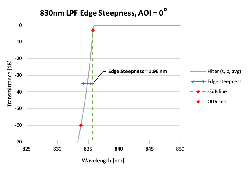
Figure showing how ‘Edge Steepness’ of a LPF is typically defined (in this case, between ¬ 3dB and -60 dB transmittance levels).
Cut-Off / “OD Blocking at the Laser Line Wavelength”
The cut-off of an edge pass filter is defined as the spectral width (specified in units of ‘%’, ‘nm’ or ‘cm‑1’) between the laser line wavelength and the wavelength corresponding to the 50% transmittance (-3 dB) point of the transmittance spectrum of the edge pass filter.
The OD blocking at the laser line wavelength specifies the minimum desired blocking that needs to be achieved at the laser line (LL) wavelength, λLL. Generally speaking, for given cut-off and desired OD blocking level at the laser line, the smaller the cut-off value, the “sharper” the filter, and the more challenging it is to fabricate such a filter.
Note that the cut-off value is relative to the laser line wavelength whereas the edge steepness is an inherent property of the filter. Achieving a specified cut-off and OD blocking at the LL requires achieving both the steepness of a filter and positioning the -3 dB edge relative to the laser line wavelength. As such, cut-off is a more demanding specification and it is more relevant to the application.
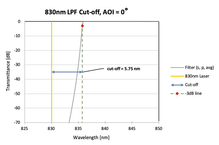
Figure showing the typical definition of the Raman filter ‘cut-off’ specification. In this example, the cut-off is 5.75 nm or it can also be specified as 82.9 cm-1.
Effect of Angle of Incidence (AOI)
The AOI is the angle between the incident beam and the normal of the surface of the filter. An AOI of 0° can also be described as “normal incidence”. For any non-zero (e.g., non-normal or oblique) AOI, the spectral edge of the filter will shift towards shorter wavelengths.
Figure showing wavelength downshift of a 830-nm LPF versus AOI for s-polarized light.
The wavelength downshift for a given AOI is both design and light polarization dependant. Light can be either linearly polarized (s- or p-polarized) or a mixture of linearly polarized light. The performance of the filter at non-normal AOI will hence depend on the degree of polarization of the light. Specifically, the wavelength downshift with AOI will be different for s- and p-polarization of light and this can lead to polarization splitting (see next section).
As shown in the figure below, increasing the AOI reduces the filter cut-off and the OD of the filter at the laser line wavelength as the spectral edge of the filter is shifted closer to the laser wavelength.
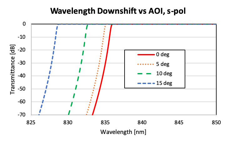
Figure showing wavelength downshift of a 830-nm LPF versus AOI for s-polarized light.
Shown in the next figure is the effect of changing the AOI of a 830-nm LPF on the subsequent change in the cut-off value and the filter OD blocking at the laser line wavelength. As can be seen, the OD blocking of the filter at the laser line wavelength quickly drops from 6.2 OD to 4 OD as AOI changes from 0° to 4°, respectively. For the same AOI change, the cut-off value drops by a factor of 2.
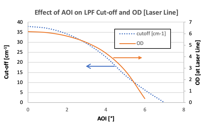
Figures showing how the cut-off off a filter and the OD [at the laser line wavelength] varies with the angle of incidence (AOI) of s-polarized light on the filter.
Polarization Splitting
As the AOI increases from normal incidence, the filter edges shift to shorter wavelengths (“blue-shift”). The edges for s- and p-polarizations shift different amounts leading to polarization splitting. For a LPF, the p-polarized spectral edge is blue-shifted more than the s-polarized spectral edge. (For a short-pass filter (SPF), the s-polarized spectral edge is blue-shifted more than the p-polarized spectral edge).
Polarization splitting results in a flat “shelf” in the spectral response of ‘average’ or ‘un-polarized’ light (a 50% mixture of s- and p-polarized light). This reduces the effective edge steepness and, therefore, the cut-off of the filter.
In the figure below, the transmittance of a LPF filter is shown for light incident at an angle of 10° for s-, p- and average-polarized light. The polarization splitting is evident where the p-polarized light is shifted further compared to the s-polarized light. With average polarization of light, the flat shelf is at a ‑3 dB (50%) level.
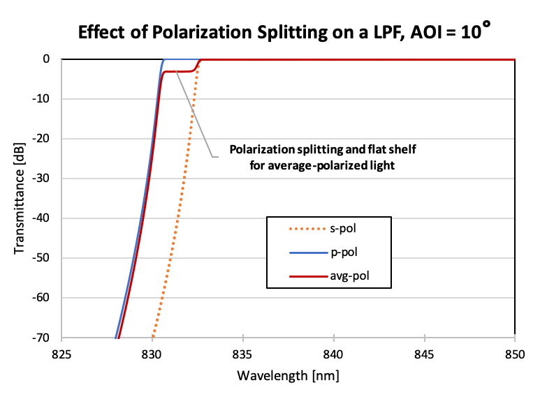
Figure showing the change in transmittance of a LPF filter for different polarization states of light (at an AOI of 10°).
Note that the flat shelf transmittance level varies with different mixtures of polarized light in the incident light; e.g., for a mixture of 80% s-polarized light and 20% p-polarized light, the transmittance of the shelf will be lower than 20%. This can be seen in the figure below: as measured from the laser line wavelength to the 50% transmittance level, the filter cut-off is 45 cm-1 for the average polarization beam (as expected) but it is 57 cm-1 for the partially s-polarized beam and 29 cm-1 for the partially p-polarized beam. In each case the filter is identical, but the cut-off varies due to the polarization of the probe beam. Hence, it is important to use the filter with the polarization state that it was designed for.
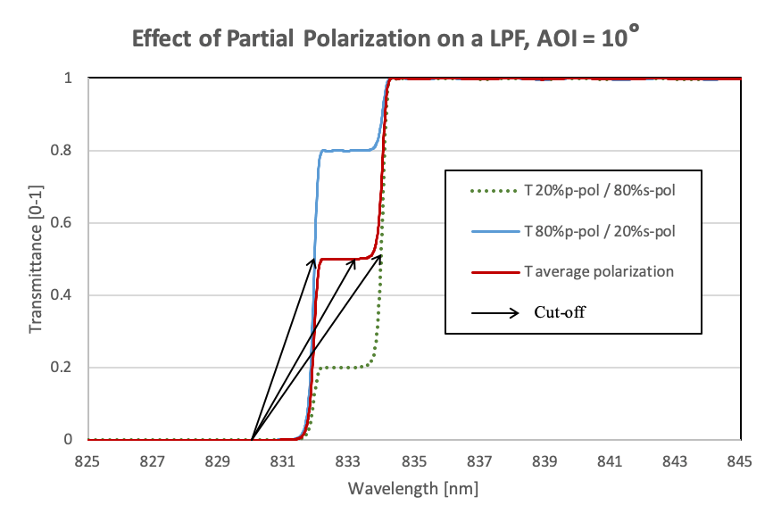
Figure showing, for a 830-nm LPF at AOI=10°, how the change in polarization in the incident light can effect the apparent filter cut-off and the ‘flat-shelf’ transmittance level.
Effect of Laser Wavelength
As mentioned previously, the filter cut-off is the wavelength difference between the laser line wavelength and the wavelength corresponding to a defined transmittance point (typically T=50% point) on the filter spectrum. For a Raman edge filter designed for a specific laser wavelength, variations in the actual laser wavelength used will affect the filter cut-off and the OD blocking at the laser line wavelength (see figure below). It is therefore very important to take into account possible variations in the laser wavelength being used in a given the application when selecting or defining the needs of a Raman edge filter.
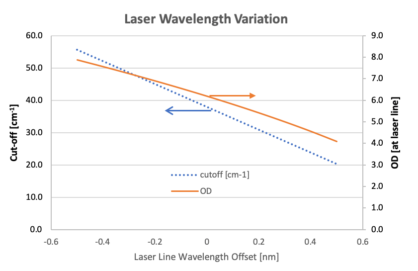
Figure showing how deviations from the laser line wavelength, for which a LPF was designed for, effects a LPF’s cut-off and OD blocking at the laser line wavelength being used. In this example, a deviation of +0.2 nm in the laser linewavelength results in the OD blocking dropping from 6.2 OD to 5.2 OD while the cut-off decreases from ~ 38 cm-1 to 30 cm-1.
For example, if a Raman LPF is used in different instruments where there may be a significant variation in the laser wavelength (i.e., more than ±0.1 nm), the LPF filter will not work as intended even though the LPF filter meets all the defined specifications.
Effect of a Light Cone
In the previous figures, it was assumed that the light on the filter was collimated. In fact, for most applications, the light incident on the filter is a mixture of light rays coming in with different relative intensities and angles of incidence. This case can be modelled by assuming a light cone is incident up a filter with different relative intensities. One can define a Cone Half Angle (θCHA) to specify the angular spread of the light for a non-collimated light source (such as an LED). The angular spread can be modelled, for example, as a Gaussian profile with a θCHA defined as the angle at which the normalized light intensity is of the maximum intensity.
The following figure shows a Gaussian profile light source with θCHA=5.5°.
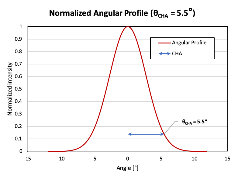
Figure illustrating a possible line cone having a Gaussian intensity profile.
The next figure shows the transmittance of a LPF when a light cone, with a Gaussian profile based on a θCHA=5.5°, and with different polarization states is incident upon the filter. As can be seen, having non-collimated light can result in a significant change in the measured transmittance of the LPF resulting in an increased edge steepness and lower OD blocking at the laser line.
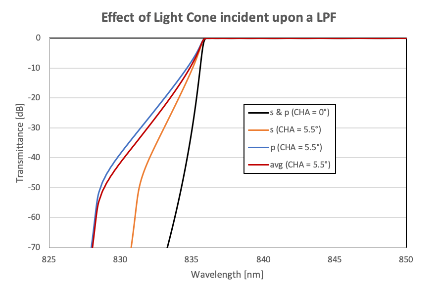
Figure showing the transmittance of LPF for a collimated beam (θCHA=0°) and for a light cone (θCHA=5.5°) for s-, p- and average-polarized light.
The figure below shows how changing a light cone’s θCHA from 0° (collimated beam) to 4° incident on a LPF changes the LPF’s cut-off and OD blocking at the laser line. In this case, the 830-nm LPF was designed to operate at a AOI=5° assuming average polarized light. As can be seen, the cut-off does not change dramatically as the -3dB wavelength does not change significantly as the light cone angle increases. However, the OD blocking at the laser line is significantly affected. The blocking changes from 6.2 OD to less than 5 OD when the half-cone angle is larger than 1.5°. Therefore, it is very important to have a good understanding of the light cone incident upon a Raman edge filter in order to obtain the desired performance. For cases where there is a substantial half-cone angle, it might be better to choose a less steep edge filter slope (and a higher filter cut-off) to ensure the Raman filter laser line blocking is maintained.
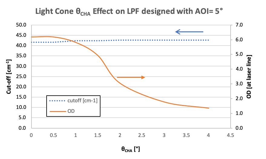
Figure showing, for a 830 nm LPF designed to be used at a AOI of 5° for average polarized light, how the cut-off and OD blocking at the laser line is affected by the half-cone angle of a light cone incident up on the LPF.
Effects of Wavelength Instrument/Detector Resolution
As previously stated, the theoretical transmittance curves of the previous filters assume that the detector/instrument wavelength resolution is negligible. However, optical metrology instruments might typically use a wavelength resolution between 0.1 nm and 2.0 nm in order to improve the signal-to-noise (S/N) ratio, especially when measuring the OD blocking of a filter. The effect of a non-zero instrument resolution on the measurement of a LPF is that the transition from passband to blocking becomes ‘rounded’. The amount of rounding is proportional to the resolution bandwidth that is used so that a higher instrument resolution (or bandwidth) corresponds to increased rounding.
In the figure below, for a LPF designed for a AOI=0°, there is significant rounding in the LPF measurement as the instrument resolution (bandwidth) is changed from 0 nm to 2 nm. At a resolution bandwidth of 2 nm, the LPF transmittance in the blocking spectral region appears to be very high. However, it is important to note, that this is a result of a measurement artifact arising from a non-zero instrument resolution. The LPF filter shape is actually okay and this can be verified if measured with a small instrument resolution (bandwidth).
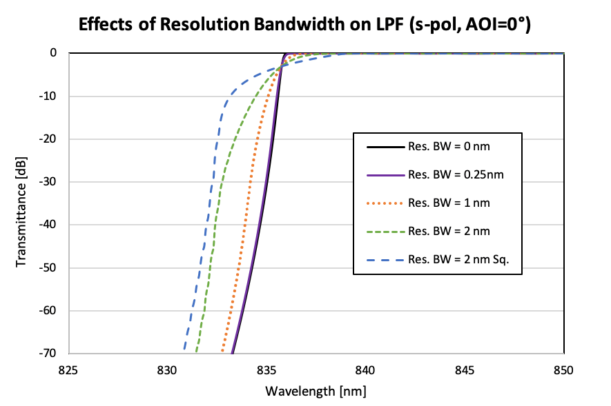
Figure showing the transmittance of a LPF when measured with different instrument resolutions.
Measurement of OD Blocking Level
It can be quite challenging to accurately measure the Optical Density (OD) of a filter down to 6 to 8 OD. If not done properly, measurement artifacts can make it appear that a Raman edge pass filter does not meet the OD blocking specification at the laser line.
Good blocking measurements can be obtained in several different ways: the best (and easiest) approach is to use a tunable laser light source for a direct measurement. Otherwise, if only a single wavelength laser is available, one can measure the transmittance by angle tuning the filter. Commercial spectrophotometers can also be used but, because they use a white light source, these instruments usually have a noise floor that can lie anywhere from 2OD to 7OD (-20 dB to -70 dB), depending on the instrument bandwidth chosen. So even if the filter is able to block lower than this noise floor level, it may not be possible to demonstrate this with these commercial spectrophotometers. As well, to get to a low noise floor (> 6 OD), it is necessary to use a large instrument resolution which can affect the measured slope of the edge pass filter leading to another type of measurement artifact).
The figure below shows the measurement of an Iridian Nano-Edge LPF with a tunable laser source. As can be seen, there is good agreement with the expected design (theory) performance. If this filter was measured with a commercial spectrophotometer, then depending on the instrument resolution, the blocking level at the laser line would have appeared to be much less – around 4 to 6 OD.
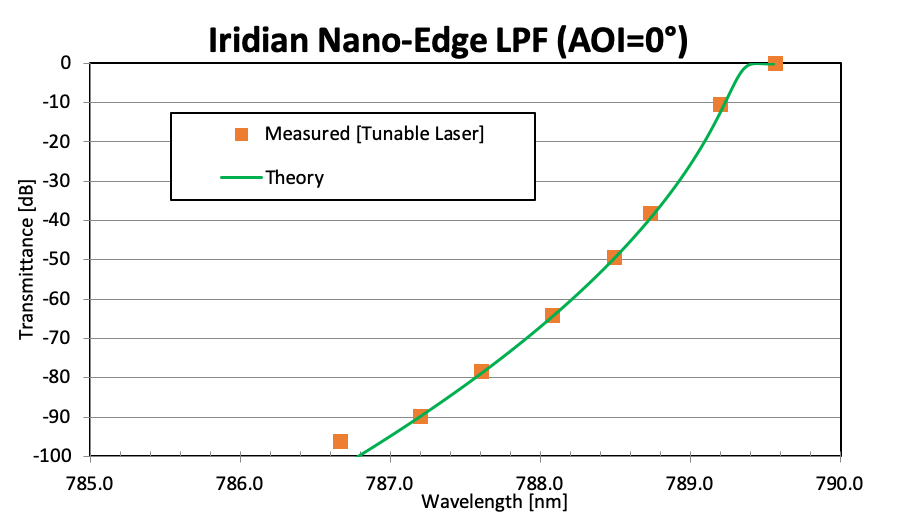
Figure showing the measured transmittance of Iridian Nano-Edge LPF using a tunable laser (orange squares) with AOI=0°. The theoretical data for the edge pass filter is also shown (green curve). As can be seen, there is an excellent agreement between theory and measurement down to around -90 dB (9 OD) after which the measurement setup with the tunable laser hits a noise floor around -95 dB.
To measure the transition from the passband to blocking spectral regions, a broadband white light source can be used with an OSA. To accurately measure this, the instrument resolution should be made as narrow as possible. The figure below shows the measured data of the same Iridian Nano-Edge filter as in the previous figure. The instrument resolution was 0.05 nm and the light beam had a cone half-angle of ~ 2°. (Note with this instrument resolution, the OD noise floor is around 2 OD). As can be seen, there is good agreement between the OSA measurement and the expected design performance.
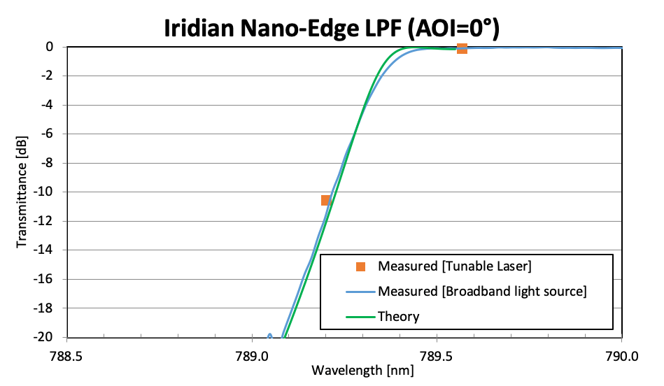
Figure showing the measured transmittance of Iridian Nano-Edge LPF using a OSA with a broadband light source (instrument resolution was 0.05 nm and a light beam had a cone angle of 2° (blue curve). The theoretical data for the edge pass filter is also shown (green curve). As can be seen, there is a very good agreement between theory and measurement down to around -20 dB (2 OD) after which the measurement setup hits a noise floor around -22 dB.
Cumulative Effects
The cumulative effects of all the above parameters that might affect the Raman edge pass filter performance (including AOI, half-cone angle, polarization, laser wavelength variation, instrument resolution) are not necessarily intuitive. For example, small changes in these individual parameters can impart a large overall change in the filter spectral performance. In general, with one or more combinations of the above effects, the measured edge steepness will decrease, the cut-off of the filter will increase, the transition edge will be more rounded and shift towards shorter wavelengths, and OD blocking level at the laser line decreases. All of this occurs even though the edge pass filter performance is as specified for a collimated light beam operating with the design laser line wavelength.
This can be demonstrated for a 830 nm LPF design filter as shown in the figure below. The ‘blue’ curve shows the expected filter performance for a well-collimated beam at AOI=0°, negligible resolution bandwidth and the laser line wavelength is as designed. The ‘orange’ curve shows the expected filter performance when the light incident upon the filter is a light cone with θCHA=5° (at an AOI=0°) and with a 1.25 nm resolution bandwidth and the laser line wavelength being +0.2 nm higher than the desired laser line wavelength (these values corresponding to a possible application of the LPF).
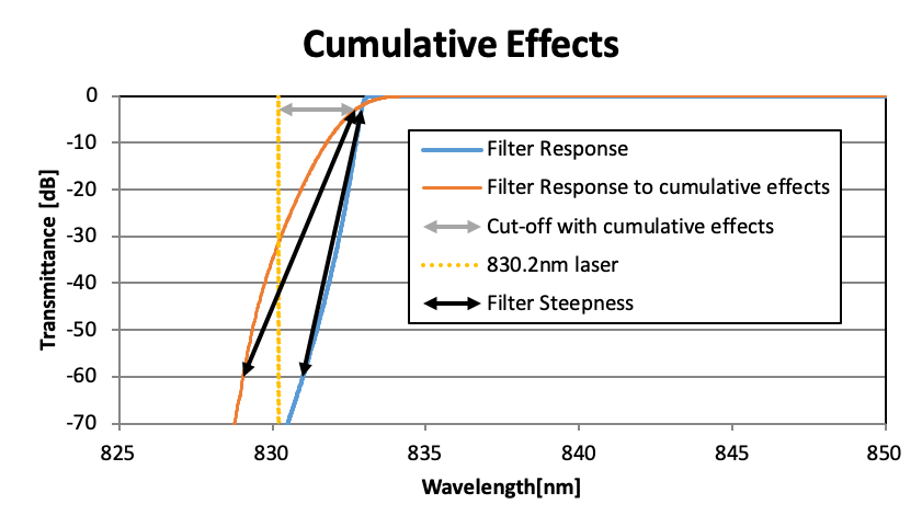
Figure showing transmittance of LPF designed for a well-collimated beam (AOI=0°, θCHA=0°, resolution bandwidth=0 nm, laser line wavelength offset = 0 nm) – ‘blue’ curve and its use in an application with a divergent beam with the laser line wavelength being different than specified (AOI=0°, θCHA=5°, resolution bandwidth=1.25, laser line wavelength offset =+0.2 nm) – ‘orange’ curve). Note that as used in this application, the OD blocking is ~ 3 OD instead of the expected > 7 OD.
The net effect is that the filter cut-off, OD blocking level and edge steepness changes drastically between these two application scenarios as shown in the table below.
| Specification Parameter | Filter performance, using as-designed | Filter performance with light cone (θCHA=5°), instrument resolution of 1.25 nm and laser line wavelength offset (+0.2nm) |
|---|---|---|
| Laser Line Blocking | 7.8 OD | 3.1 OD |
| Cut-Off | 2.9 nm (42 cm-1) | 2.5 nm (36 cm-1) |
| Edge Steepness (6 OD to 50%) | 1.9 nm | 3.7 nm |
Table showing the large change in laser line blocking level, cut-off and edge steepness as the light cone half-angle is changed; AOI is changed; laser line wavelength offset is introduced; and there is a non-zero instrument bandwidth.
Note that it is possible to design the LPF to allow for the light cone incident on the filter. This is shown in the figure below where the blocking level is now better than 6 OD at the laser line wavelength.
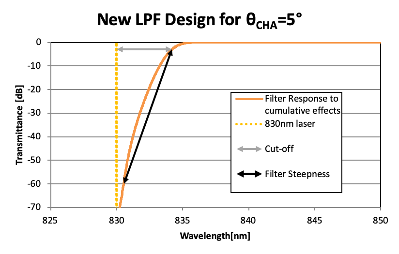
Figure showing transmittance of LPF designed for (AOI=0°, θCHA=5°, resolution bandwidth=1.25 nm) – ‘orange’ curve. Max cut-off is 4.2 nm (61 cm-1), minimum 6 OD blocking
Summary
The intent of this technical note is to first ensure that that the technical definitions used when describing a Raman edge pass filter are well understood and then to ensure that users understand how the measured performance of a filter will depend on how it is used in an application.
In particular, selecting the optimum edge steepness, filter AOI filter cut-off and OD blocking level will depend on i) the properties of the light incident upon the filter (polarization, half-cone angle); ii) any variation in the laser line wavelength; iii) and the detector resolution (bandwidth) being used in the application. As well, if measuring the filter on a spectrophotometer to verify the performance of a filter, it is important to understand the effects of the spectrophotometer light cone, polarization state and the instrument resolution (bandwidth) on the measured transmittance (as measurement artifacts can sometimes make it appear that an edge pass filter does not meet specification).
Please contact Iridian for more details or for assistance in choosing the optimum edge pass filter for a given application.
Iridian Spectral Technologies Ltd (Iridian) is a diversified optical filter manufacturer that is an international leader in filter design and manufacture especially for application in the fields of fiber optic communications, optical spectroscopy, 3D entertainment, and in aerospace. Iridian is a global supplier with distributors in many countries.